

Vertical Filling Machine Engineering Guide: Principles, Sizing, and Integration of Modern VFFS Systems
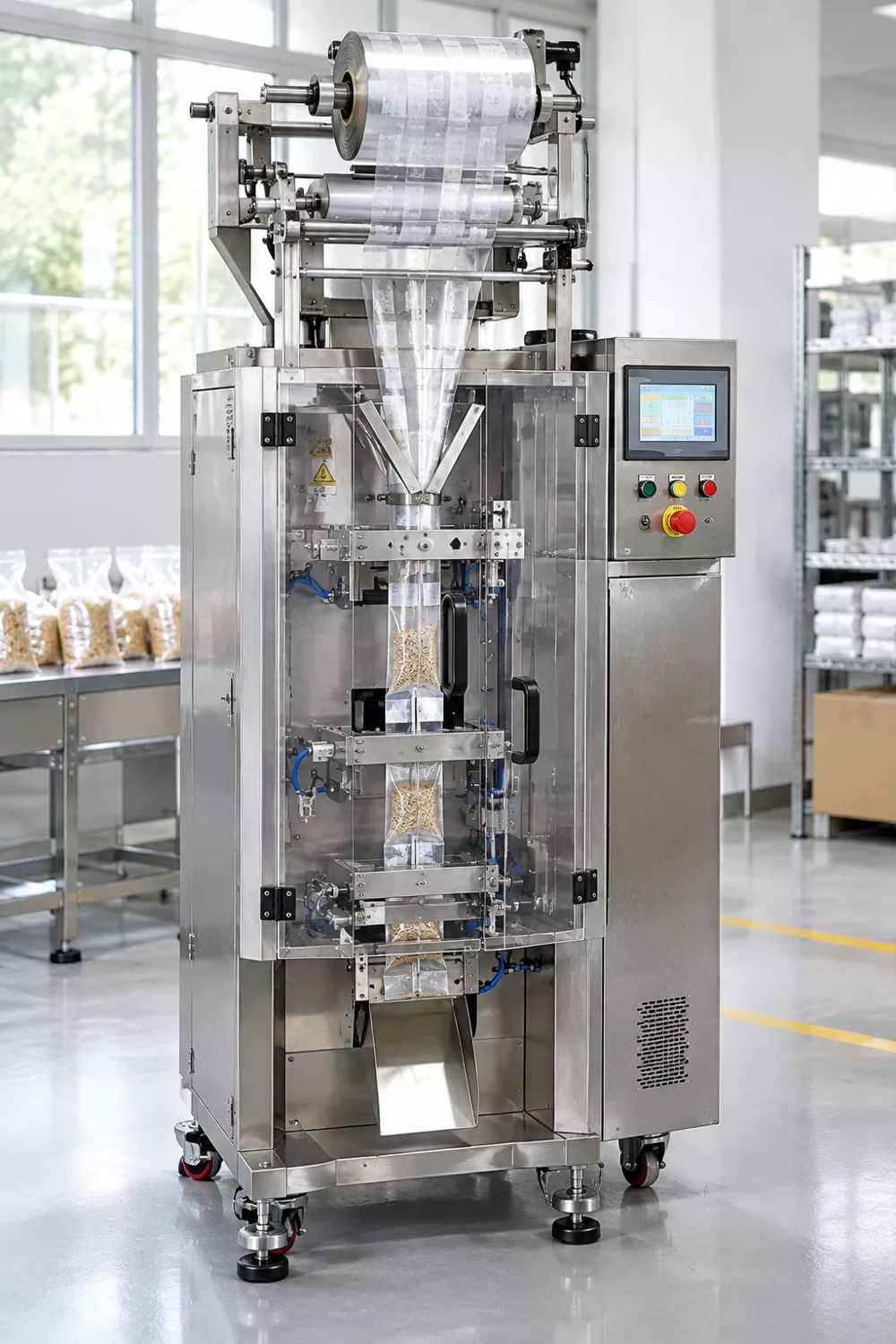
Operating an automated packaging line requires dependable management over film tension, sealing thermodynamics, and product flow dynamics. A vertical filling machine, often known in packaging engineering as a vertical form fill and seal (VFFS) system, transforms flat rollstock film into finished pouches while dosing bulk products in a single automated drop. Whether handling granular food, agricultural chemicals, or pharmaceutical powders, plant operators face persistent challenges such as seal seam defects, web wander, and film wrinkling during production runs. Selecting the right vertical filling machine architecture determines whether a facility achieves stable output or suffers from frequent mechanical stoppages and product giveaway.
Modern vertical packaging lines balance flexible pouch geometry against web tracking stability under variable operating conditions. When processing multi-layer barrier laminates, minor variations in surface friction, environmental humidity, or pneumatic line pressure can shift the seal boundary across successive machine cycles. Understanding the core mechanics of film forming, vertical drop synchronization, and jaw thermal management allows production engineers to maintain steady throughput, reduce scrap rates, and optimize overall equipment effectiveness across diverse sachet and bag formats.
1. Defining the Vertical Filling Machine: Mechanism and Operational Scope
1.1 VFFS Fundamentals: Transitioning from Rollstock Film to Finished Pouches
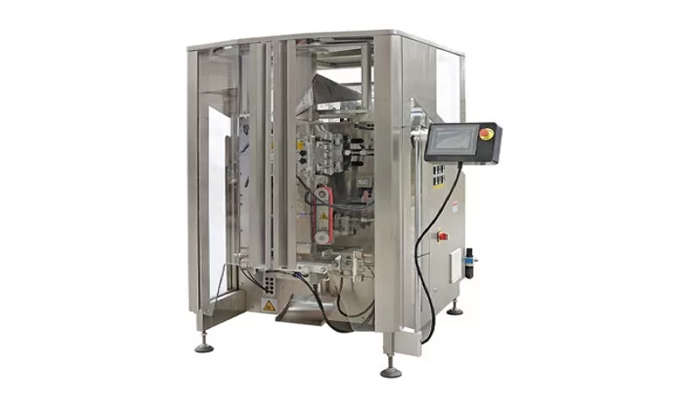
A vertical form fill seal system converts continuous flexible packaging film into sealed, portioned containers through synchronized vertical motions. In contrast to manual dispensers or linear multi-head weighers operating without integrated web handling, this packaging platform incorporates roll unwind, collar folding, longitudinal sealing, product filling, and transverse cutting within a compact vertical footprint, making efficient use of available plant floor space.
The basic cycle relies on gravitational acceleration to transfer dosed materials into each newly formed pouch sleeve. As the flexible web passes over a forming shoulder, it drapes into a continuous tube around the hollow forming mandrel. Material drops through the center of the forming tube directly into the pouch interior, while cross-sealing jaws execute the bottom closure of the incoming bag simultaneously with the top closure of the preceding container.
1.2 Three-Side vs. Four-Side Seal Architecture
Pouch geometry dictates structural handling characteristics and visual presentation on retail shelves. A three-side seal sachet uses a single continuous film web folded along one longitudinal edge, requiring only one longitudinal seam and two transverse cross seals. This geometry maximizes internal holding volume relative to overall film consumption, making it an economical choice for single-serve condiments, seasonings, chemical trial packets, and promotional sample sachets.
A four-side seal format features perimeter bonded seals around all four outer edges of the finished container. Depending on product characteristics and laminate stiffness, this four-sided edge perimeter can provide a defined rectangular profile that holds its shape during shelf merchandising or secondary carton packing. The resulting flat face provides a uniform visual display surface for consumer branding, pharmaceutical labeling, and required regulatory ingredient statements.
The CB-VS36 platform is listed by the equipment manufacturer for producing both three-side and four-side sealed pouches. Because specific former tooling, jaw configurations, and film feeding arrangements vary depending on pouch dimensions and material structure, plant engineers should confirm necessary conversion components, changeover tooling, and machine configurations directly with the equipment manufacturer before planning multi-format production schedules.
2. Critical Mechanical Subsystems and Kinematics
2.1 Film Web Control: Servo-Driven Vacuum Pulling vs. Mechanical Belts
Film draw belts must advance the packaging substrate through the machine without slippage or surface scuffing on delicate printed exterior layers. Traditional mechanical draw systems rely on friction rubber belts pressed against opposing sides of the forming tube. While mechanically straightforward, friction belts depend entirely on surface traction, which can degrade over time as environmental dust, processing fines, or product powders settle onto the belt faces.
Servo-driven vacuum pulling systems supplement contact friction by drawing negative air pressure through perforations located along the face of each drive belt. The applied vacuum holds the moving film firmly against the belt surface, distributing tensile draw forces across a broader contact area. Depending on film structure and operating parameters, this arrangement can assist in stabilizing web transport on packaging films within the 0.04 mm to 0.09 mm thickness range.
2.2 Forming Tube Dynamics and Anti-Folding Jaws
The forming collar acts as a critical geometric transition zone, reshaping a planar web of flexible film into a cylindrical or rectangular tube. If the entry curve or collar shoulders exhibit uneven profiles or improper alignment, lateral stress concentrations can induce diagonal wrinkles that migrate directly into the vertical sealing zone. A properly designed and mounted forming collar ensures smooth, unforced film convergence without edge stretching.
During transverse sealing, wide or thin pouches can develop dog-ear folds or pleats at outer corners as the horizontal sealing jaws close together. The CB-VS36 incorporates an anti-folding device designed to mechanically guide lateral film edges during horizontal sealing. This assists in keeping the film flat as the jaws meet, supporting consistent seal formation across both three-side and four-side packaging formats.
2.3 Optoelectronic Eye-Mark Tracking and Automated Edge Correction
Print registration and lateral web tracking address distinct aspects of flexible film handling during continuous production. Printed rollstock relies on optoelectronic eye-mark registration sensors to detect printed timing marks on the web margin, signaling vertical pouch pitch and triggering transverse cut positions relative to the artwork. Without dependable cut timing, printed package graphics can drift progressively along the vertical pouch column.
Lateral web wander represents a separate mechanical variable that occurs when rollstock shifts axially across the unwind spindle due to uneven core winding or tension variances. The CB-VS36 is equipped with a manufacturer-listed automatic correction system intended for high-precision tracking and accurate bag positioning. Plant engineers should review the specific sensing hardware, correction axes, and web-guide operating parameters directly with the equipment supplier during commissioning.
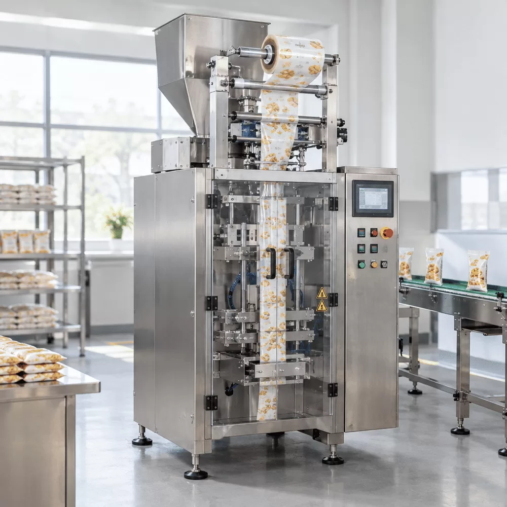
3. Equipment Sizing and Technical Specifications: Evaluating the CB-VS36
3.1 Dimensional Capacity and Film Geometry Analysis
Matching machine dimensions to production requirements requires strict adherence to physical geometry limits and material properties. The CB-VS36 platform accommodates a maximum packaging film width of 360 mm, with listed bag length capabilities from 60 mm to 180 mm and bag widths from 50 mm to 260 mm. Usable pouch capacity, gusset configurations, and target fill volumes must be validated against the specific former, film layout, and machine setup.
Pouch volume calculations must also account for bulk density changes during dynamic material transfer. When aerated powders or loose granular goods drop through the former tube, their dynamic bulk density is frequently lower than their final settled state within the finished container. The forming tube cross-section must be matched to pouch dimensions and product flow properties, with achievable line speeds confirmed through empirical application trials.
3.2 Machine Parameter Overview
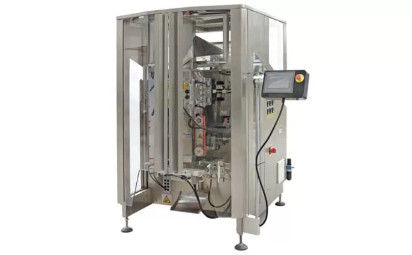
For facilities evaluating standard industrial packaging machinery, Baopack manufactures automated form fill seal solutions designed for diverse pouch formats. Selecting appropriate equipment requires aligning line footprint, electrical hookups, pneumatic supply, and dimensional capacity with plant infrastructure. Technical specifications for the CB-VS36 model are detailed in the following overview based on manufacturer documentation:
| Technical Parameter | Specification / Rating |
|---|---|
| Machine Model | CB-VS36 |
| Maximum Packaging Speed | Maximum 40 bags/min |
| Bag Length Range | 60 mm to 180 mm |
| Bag Width Range | 50 mm to 260 mm |
| Sealing Configuration | 3-side or 4-side sealing |
| Maximum Packaging Film Width | 360 mm |
| Compatible Film Thickness | 0.04 mm to 0.09 mm |
| Operating Air Pressure | Listed pressure: 0.8 MPa (per manufacturer data) |
| Listed Air Consumption Figure | 0.3 cmb/min (confirm delivery flow with supplier) |
| Electrical Power Requirements | 3.3 kW, 220 V, 50 Hz / 60 Hz |
| Machine Physical Dimensions | L 1140 mm × W 1460 mm × H 1470 mm |
3.3 Speed Ceilings vs. Sustained Operating Rates
The manufacturer lists a maximum speed of 40 bags per minute. In commercial production environments, actual throughput fluctuates based on product discharge rates, pouch dimensions, film thermal properties, and requisite sealing dwell times. Operating teams should establish target production rates based on application-specific testing rather than assuming constant peak line speeds, since mechanical ceilings reflect specific baseline parameters.
Material flowability directly governs overall packaging cycle duration. Free-flowing dry goods discharge rapidly through the forming column, permitting shorter dwell intervals during the filling phase. In contrast, cohesive powders, sticky dried goods, or viscous liquids require deliberate pause times to settle fully into the pouch base. Attempting to cycle the machine faster than product flow allows leads to seal margin contamination and frequent downtime.
4. Upstream Dosing Integration: Powders, Granules, and Viscous Materials
4.1 Granular Products: Volumetric Cups and Multi-Head Weighers
Granular products such as agricultural seeds, plastic pellets, confectioneries, and dry beans require rapid, repetitive volumetric or gravimetric batching upstream of the bagger. Multi-head weighers utilize individual load-cell hoppers to combine fractional product charges into an accurate target dose, discharging bulk batches synchronously with the vertical form fill seal draw cycle.
Precise timing coordination between the feeder discharge gate and the former opening is essential for seamless operation across repetitive cycles. A programmable interface trigger releases the product charge just as the packaging film completes its downward index stroke. This synchronized release helps prevent falling product pieces from colliding with closing horizontal seal bars, reducing seal damage, pouch punctures, and mechanical obstructions in high-speed lines.
4.2 Fine Powders: Auger Screw Metering and Dust Abatement
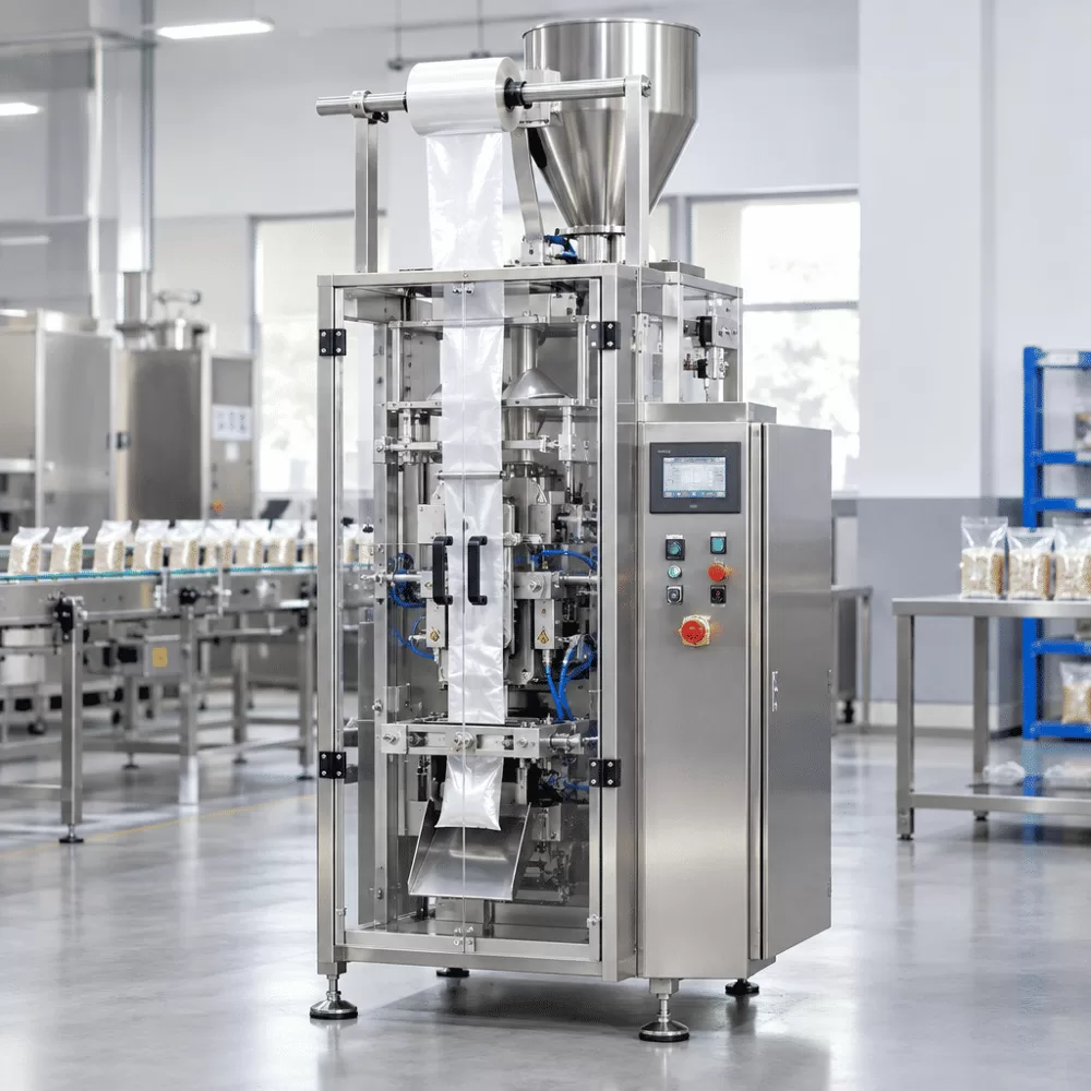
Non-free-flowing powders such as wheat flour, cornstarch, cocoa, and industrial chemical pigments resist gravitational dropping, adhering to inner former surfaces and generating airborne particulate clouds. Auger fillers resolve this conveying challenge by driving consistent volumes of powder downward through a rotating precision flight screw housed within a matched discharge funnel.
Depending on powder characteristics, plant ambient humidity, and line integration requirements, engineering teams can evaluate several dust-mitigation options to support seal integrity:
- Dust extraction ports: Overhead vacuum hoods mounted near the forming tube collar help collect suspended fines before they settle onto open film margins.
- Nozzle cut-off mechanisms: Pneumatic or mechanical flap gates fitted at the auger exit help prevent post-dosing powder dribble between successive filling cycles.
- Static neutralization bars: Ionizing bars positioned along the unwinding film web neutralize electrostatic surface charges that otherwise cause airborne dust particles to adhere to inner sealant layers.
4.3 Viscous Pastes and Liquids: Piston Pump and Flow Meter Compatibility
Packaging liquid condiments, viscous pastes, cosmetic lotions, or fluid chemicals introduces hydrodynamic forces and splashing hazards into the vertical forming environment. Positive displacement piston pumps draw fluid from an adjacent supply reservoir and deliver metered volumetric strokes, subject to pump calibration and product conditions, into the vertical tube through a submerged discharge lance that extends into the forming area.
Positive shut-off nozzles help prevent viscous liquids from dripping across open transverse film bands prior to jaw closure. Liquid film contamination across the heat-seal area can create micro-channels that compromise shelf-life packaging integrity. Lance vertical positioning must be calibrated so liquid releases near the base of the pouch without generating turbulent upward splashes onto the sealing plane.
5. Film Substrates, Thermal Sealing, and Quality Verification
5.1 Laminate Compatibility and Thermal Transfer Dwell Time
Flexible packaging substrates typically combine multiple structural layers, such as reverse-printed biaxially oriented polypropylene (BOPP) or polyethylene terephthalate (PET) laminated to an inner low-density polyethylene (LDPE) or cast polypropylene (CPP) heat-seal layer. Outer layers may provide printability, stiffness, barrier, or mechanical protection, while the inner sealant layer is selected to form the heat seal under thermal compression.
Achieving consistent seal bonding requires balanced adjustment of jaw temperature, dwell time, and mechanical clamping pressure across production shifts. Thermal settings must be validated experimentally for the specific laminate structure, film thickness range (such as 0.04 mm to 0.09 mm on the CB-VS36), and planned line cycle frequency. Electronic PID temperature controllers help regulate jaw heating elements to achieve solid bonding without burning outer layers during normal operation.
5.2 Sealing Integrity Testing and Defect Prevention
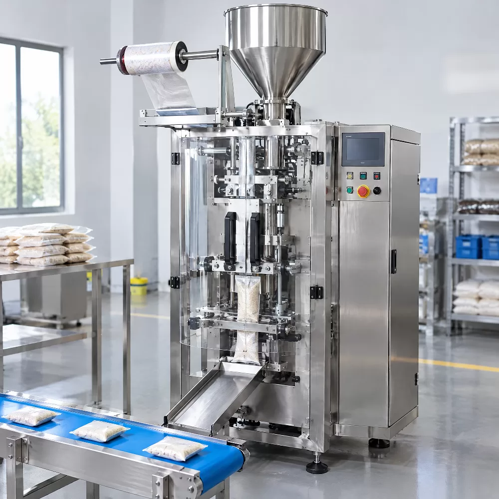
Verifying package integrity across commercial supply chains requires validated quality inspection methods suited to the pouch format, headspace volume, and product barrier specifications. Packaging engineering teams should select and validate appropriate testing procedures based on recognized industry standards:
- Visual alignment check: Inspect finished pouch margins under proper lighting for transverse seal offsets, fold wrinkles, uneven cooling marks, or asymmetric guillotine cuts.
- Mechanical peel evaluation: Peel open cooled seams according to standardized tensile testing protocols to measure seal strength and record the observed failure mode against the package-specific acceptance criteria.
- Vacuum-chamber bubble-emission testing: Submerge test pouches containing headspace gas in an acrylic vacuum water chamber per ASTM D3078; continuous air bubble streams reveal gross leaks under the selected test conditions.
- Dye penetration examination: Apply low-viscosity penetrant dye along pouch seal margins following established test standards to detect capillary leak pathways across transverse and longitudinal heat crimps.
6. Sizing, Commissioning, and Safety Protocols
6.1 Factory Footprint, Utility Dropping, and Pneumatic Preparation
Installing a vertical filling machine requires adequate spatial clearances and stable utility drops across the operating envelope to support routine access. The CB-VS36 features machine dimensions of 1,140 mm in length, 1,460 mm in width, and 1,470 mm in overall height. Sufficient overhead clearance must also remain unobstructed above the machine structure to accommodate dosing funnels, transition chutes, weigh scales, and maintenance service platforms.
Pneumatic supply stability directly influences horizontal jaw clamping uniformity and cutoff knife actuation. The manufacturer lists an operating air pressure of 0.8 MPa and an air consumption figure of 0.3 cmb/min. Because "cmb/min" represents an unconfirmed unit notation, plant engineers should confirm the required delivery flow rate with the equipment supplier before finalizing pneumatic piping. Clean, dry compressed air routed through an external regulator and moisture filter prevents valve contamination.
6.2 Maintenance Routines and Hazardous Energy Control
Mechanical drive linkages and thermal sealing components require scheduled preventive maintenance to maintain consistent operating performance over extended service cycles. Maintenance supervisors should institute disciplined inspection protocols across daily and weekly production shifts:
- Surface residue cleaning: Clean sealing jaw profiles and guillotine cut blades according to manufacturer guidelines using approved non-abrasive tools to avoid scratching treated metal contact surfaces.
- Vacuum belt inspection: Clear accumulated dust and debris from vacuum belt suction orifices, checking drive belts for uneven mechanical wear or loss of traction.
- Pneumatic filter purging: Drain moisture condensates from incoming pneumatic bowl filters and verify system operating pressure against machine specifications.
- Hazardous energy isolation: Prior to cleaning jaws, servicing cutter blades, or entering internal mechanical drive compartments, technicians must follow site-specific lockout/tagout (LOTO) protocols, isolating and verifying all electrical, pneumatic, and stored mechanical energy sources.
Frequently Asked Questions (FAQs)
What is the primary difference between a vertical filling machine and a horizontal flow wrapper?
A vertical form fill seal machine creates a vertical tube of packaging film and uses gravitational acceleration to drop bulk products directly into the pouch before closing the top seal. This vertical architecture makes it well suited for packaging loose granules, fine powders, liquids, and bulk parts. A horizontal flow wrapper advances discrete solid items horizontally along an infeed conveyor into an open horizontal film wrap, making it suitable for solid items like snack bars, cookies, bakery items, trays, and individual industrial components.
Can the CB-VS36 machine handle both three-side and four-side seal bags on the same frame?
Yes, the CB-VS36 is listed by the manufacturer for producing both three-side and four-side seal pouch configurations on a single machine frame. Because converting between these bag styles can involve changing the forming collar, adjusting web routing, or reconfiguring the sealing jaw assemblies, operating facilities should review specific conversion steps, tooling requirements, and mechanical changeover procedures directly with the equipment manufacturer.
Why does film thickness affect packaging speed?
Packaging film thickness directly influences thermal transfer rates from the heated metal jaws through outer barrier substrates to the inner sealant polymer layer. Thicker packaging films, such as laminates approaching 0.09 mm, require longer dwell intervals or elevated jaw temperatures to transfer sufficient heat into the sealing interface. This extended thermal transfer requirement naturally lengthens overall cycle times compared to thinner, faster-sealing film constructions.
How does an anti-folding device improve horizontal seal quality?
During transverse sealing jaw closure, flexible or wide packaging films can curl, stretch, or bunch at the outer pouch margins due to rapid mechanical compression. An anti-folding device mechanically stabilizes and guides the lateral film edges inward immediately before the sealing bars complete their contact stroke. This controlled guiding minimizes corner pleating and unwanted folds, supporting clean, uniform seal contact across the horizontal seam.
What utility connections are required before installing a vertical form fill seal system?
A standard installation requires a dedicated electrical power drop matching machine nameplate specifications, such as 3.3 kW at 220 V and 50 Hz or 60 Hz. Plant engineers should verify the supply phase and connection requirements directly from the manufacturer nameplate prior to installation. Facilities must also provide a dry, regulated compressed air connection meeting the 0.8 MPa operating pressure, confirmed with appropriate supply capacity to ensure consistent pneumatic valve actuation.
Summary and Strategic Selection Roadmap
Selecting and integrating automated packaging machinery requires a structured evaluation of container formats, material behaviors, and plant operational parameters. Production planners must evaluate target pouch dimensions, product bulk density variations, required hourly production quotas, and film barrier specifications before finalizing an equipment platform. Investing in robust film handling features—such as servo-driven vacuum pull belts, automatic tracking correction, and anti-folding sealing assemblies—helps reduce packaging film waste, protect seal integrity, and control unscheduled line stoppages.
A properly sized and calibrated vertical filling machine forms the core of an efficient packaging line across bulk food processing, agricultural packaging, chemical packing, and pharmaceutical manufacturing facilities. By matching upstream dosing systems to product rheology, adhering strictly to preventive maintenance schedules, and verifying operating parameters against material specifications, manufacturing teams can maintain dependable packaging throughput, consistent fill accuracy, and professional pouch presentation across demanding industrial production environments.


-
VFFS Equipment: The Ultimate Guide to Vertical Form Fill Seal Technology
13-03-2026 -
The Essential Guide to Weight Packing Machines for Precision Weighing
12-03-2026 -
Power Packing Machine: The Ultimate Guide to Heavy-Duty Packaging Efficiency
11-03-2026 -
Weigher Packing Machine: The Definitive Guide to Precision Weighing & Packaging
10-03-2026 -
Auger Type Powder Filling Machine: The Ultimate Guide to Precision Packaging
09-03-2026 -
Advanced Packing Solutions: Snacks, Sugar, and Frozen Food Machines
29-10-2025 -
Efficient and Reliable Solutions for Salt, Nuts, and Frozen Dumplings Packing
29-10-2025 -
High-Performance Biscuits, Lollipop, and Ketchup Packing Machines for Modern Food Production
29-10-2025 -
Efficient Liquid Filling and Packing Machines for Modern Production
23-10-2025 -
Reliable Granule Packaging Machines for Efficient Production
23-10-2025
